Productos
micro:bit GPIO expansion board
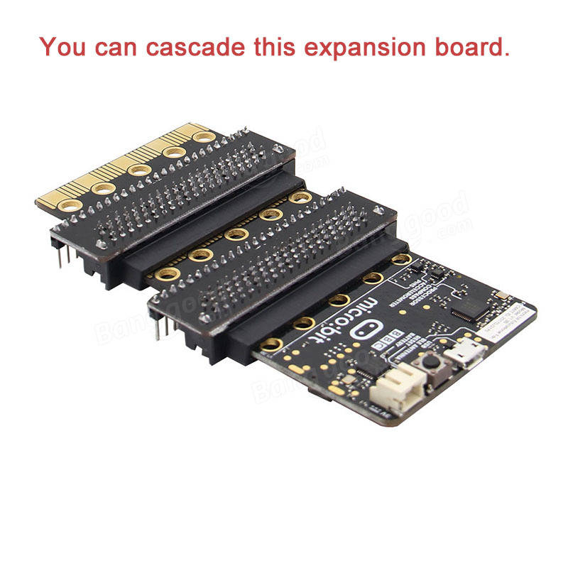
Placa de expansión GPIO para la Micro:bit. Ofrece la posibilidad de conexión en cascada. Incluye hilo conductor y juego de tornillos y tuercas para sujeción a la placa micro:bit.
COD: OKY900B-1
Peso: 0.015 Kg
Disponibilidad: Sin Stock
ARS 6213.00
El producto no está disponible para la venta en este momento
Características
Description:
Specifications:
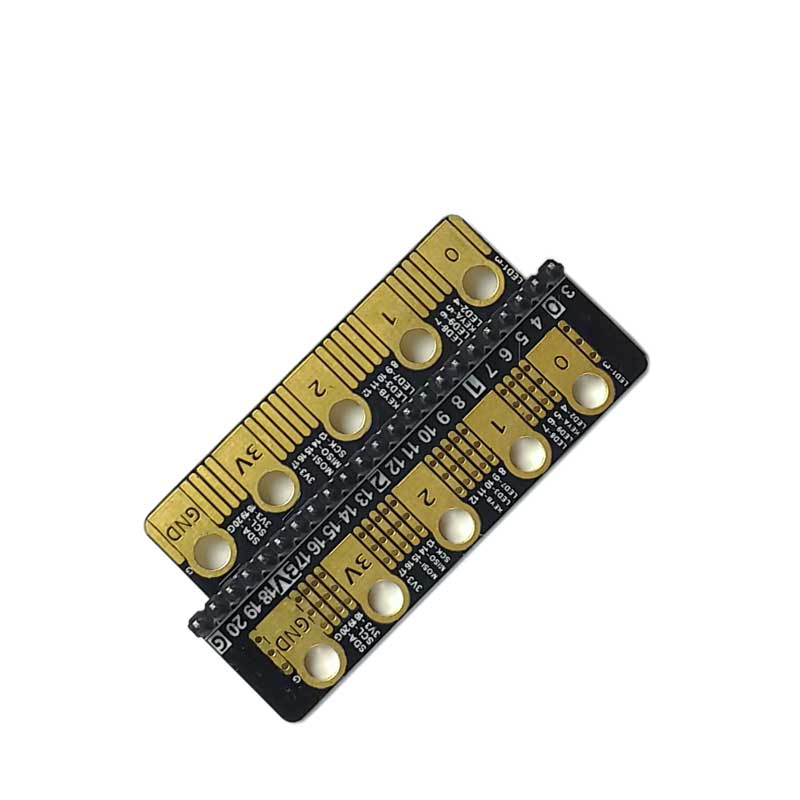
There are 20 small pins numbered sequentially from 3-22.
Unlike the three large pins that are dedicated to being used for external connections, some of the small pins are shared with other components on the BBC micro:bit board. For example, pin 3 is shared with some of the LEDs on the screen of the BBC micro:bit, so if you are using the screen to scroll messages, you can’t use this pin as well.
- pin 3: GPIO shared with LED Col 1 of the LED screen; can be used for ADC and digital I/O when the LED screen is turned off.
- pin 4: GPIO shared with LED Col 2 of the LED screen; can be used for ADC and digital I/O when the LED screen is turned off.
- pin 5: GPIO shared with Button A. This lets you trigger or detect a button "A" click externally. This pin has a pull-up resistor, which means that by default it is at voltage of 3V. To replace button A on the BBC micro:bit with an external button, connect one end of the external button to pin 5 and the other end to GND. When the button is pressed, the voltage on pin 5 is pulled down to 0, which generates a button click event.
- pin 6: GPIO shared with LED Col 9 of the LED screen; can be used for digital I/O when the LED screen is turned off.
- pin 7: GPIO shared with LED Col 8 of the LED screen; can be used for digital I/O when the LED screen is turned off.
- pin 8: Dedicated GPIO, for sending and sensing digital signals.
- pin 9: GPIO shared with LED Col 7 of the LED screen; can be used for digital I/O when the LED screen is turned off.
- pin 10: GPIO shared with LED Col 3 of the LED screen; can be used for ADC and digital I/O when the LED screen is turned off.
- pin 11: GPIO shared with Button B. This lets you trigger or detect a button “B” click externally.
- pin 12: Dedicated GPIO, for sending and sensing digital signals.
- pin 13: GPIO that is conventionally used for the serial clock (SCK) signal of the 3-wire Serial Peripheral Interface (SPI) bus.
- pin 14: GPIO that is conventionally used for the Master In Slave Out (MISO) signal of the SPI bus.
- pin 15: GPIO that is conventionally used for the Master Out Slave In (MOSI) signal of the SPI bus.
- pin 16: Dedicated GPIO (conventionally also used for SPI ‘Chip Select’ function).
- pins 17 and 18: these pins are wired to the 3V supply, like the large ‘3V’ pad.
- pins 19 and 20: implement the clock signal (SCL) and data line (SDA) of the I2C bus communication protocol. With I2C, several devices can be connected on the same bus and send/read messages to and from the CPU. Internally, the accelerometer and the compass are connected to i2c.
- pins 21 and 22: these pins are wired to the GND pin and serve no other function.
The expansion board is through the screw pressure to install the expansion board, it will inevitably lead to bad contact situation,
This kit protects against the bad connection:
- with hexagon screw and hexagonal wrench,avoid to cause slipped screw head
- Gold plating make touching easy
- Mount the copper wire at the hole of the expansion board to add touching area


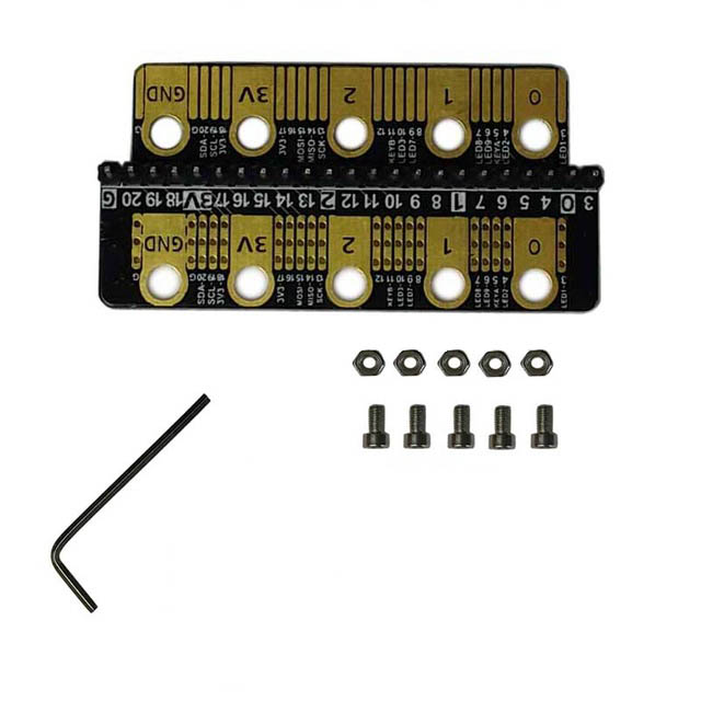
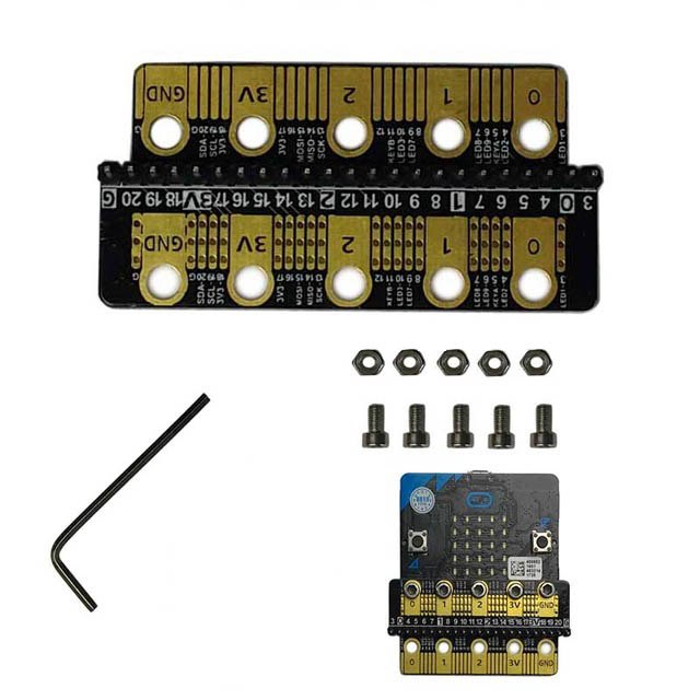
Package Contains:
- Micro:bit expansion board (A) x1.
- M3 Screw x 5.
- M3 Nuts x 5.
- Copper wire x 1.
- Allen wrench x 1.