Productos
QTR-8A Reflectance Sensor Array
Array de sensores de reflectancia analógicos (8 en total), ideales para detección de bordes o para seguimiento de línea.
COD: P000960
Peso: 0.000 Kg
Disponibilidad: Sin Stock
ARS 18026.00
El producto no está disponible para la venta en este momento
Características
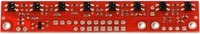
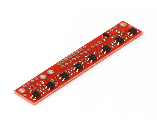
This sensor module has 8 IR LED/phototransistor pairs mounted on a 0.375" pitch, making it a great detector for a line-following robot. Pairs of LEDs are arranged in series to halve current consumption, and a MOSFET allows the LEDs to be turned off for additional sensing or power-savings options. Each sensor provides a separate analog voltage output.
Note: The QTR-8A reflectance sensor array requires analog inputs to take readings. The similar QTR-8RC reflectance sensor array is available with digital I/O-compatible outputs, and the reflectance sensor is available individually as a QTR-1A reflectance sensor or QTR-1RC reflectance sensor.
Functional Description
The QTR-8A reflectance sensor array is intended as a line sensor, but it can be used as a general-purpose proximity or reflectance sensor. The module is a convenient carrier for eight IR emitter and receiver (phototransistor) pairs evenly spaced at intervals of 0.375" (9.525 mm). Each phototransistor is connected to a pull-up resistor to form a voltage divider that produces an analog voltage output between 0 V and VIN (which is typically 5 V) as a function of the reflected IR. Lower output voltage is an indication of greater reflection.
The outputs are all independent, but the LEDs are arranged in pairs to halve current consumption. The LEDs are controlled by a MOSFET with a gate normally pulled high, allowing the LEDs to be turned off by setting the MOSFET gate to a low voltage. Turning the LEDs off might be advantageous for limiting power consumption when the sensors are not in use or for varying the effective brightness of the LEDs through PWM control.
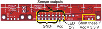
The LED current-limiting resistors for 5 V operation are arranged in two stages; this allows a simple bypass of one stage to enable operation at 3.3 V. The LED current is approximately 20-25 mA, making the total board consumption just under 100 mA. The schematic diagram of the module is shown below:
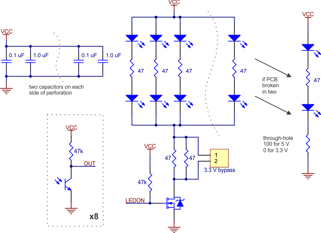 |
For a similar array with three sensors, consider our QTR-3A reflectance sensor array. The sensors on the QTR-8A are also available individually as the QTR-1A reflectance sensor, and the QTR-L-1A is an alternative designed to be used with the board perpendicular to the surface.
 |
|
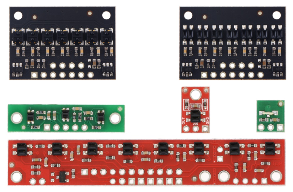
QTR sensor size comparison. Top row: QTRX-HD-07, QTR-HD-07; middle row: QTR-3, QTR-1, QTR-L-1; bottom row: QTR-8. |
|---|
Specifications
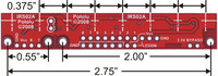
- Dimensions: 2.95" x 0.5" x 0.125" (without header pins installed)
- Operating voltage: 3.3-5.0 V
- Supply current: 100 mA
- Output format: 8 analog voltages
- Output voltage range: 0 V to supplied voltage
- Optimal sensing distance: 0.125" (3 mm)
- Maximum recommended sensing distance: 0.25" (6 mm)
- Weight without header pins: 0.11 oz (3.09 g)
Interfacing with the QTR-8A Outputs
There are several ways you can interface with the QTR-8A outputs:
- Use a microcontroller’s analog-to-digital converter (ADC) to measure the voltages.
- Use a comparator with an adjustable threshold to convert each analog voltage into a digital (i.e. black/white) signal that can be read by the digital I/O line of a microcontroller.
- Connect each output directly to a digital I/O line of a microcontroller and rely upon its internal comparator.
Our Pololu AVR library provides functions that make it easy to use these sensors with our Orangutan robot controllers; please see the QTR Reflectance Sensors section of our library command reference for more information. We also have a Arduino library for these sensors.
Breaking the Module in Two
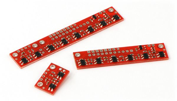
If you don’t need or cannot fit all eight sensors, you can break off two sensors and still use all 8 sensors as two separate modules, as shown below. The PCB can be scored from both sides along the perforation and then bent until it snaps apart. Each of the two resulting pieces will function as an independent line sensor.
 |
Included Components
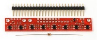
This module ships with a 25-pin 0.1" header strip and a 100 Ohm through-hole resistor as shown below.
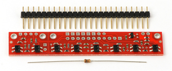 |
You can break the header strip into smaller pieces and solder them onto your reflectance sensor array as desired, or you can solder wires directly to the unit or use a right-angle header strip for a more compact installation. The pins on the module are arranged so that they can all be accessed using either an 11×1 strip or an 8×2 strip.
The resistor is required to make the two-sensor array functional after the original eight-sensor array is broken into two pieces. This resistor is only needed once the board has been broken.
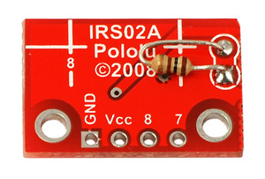 |
|
Solder the included resistor to the 2-sensor array piece as shown to make the separated piece functional. |
|---|
File downloads
- Datasheet for Fairchild’s QRE1113GR reflective object sensor (202k pdf)
- This is the sensor that we initially used in the Pololu QTR reflectance sensors, but we have since switched to a similar generic unit that has slightly longer range.
- QTR-8x Reflectance Sensor Array drill guide (35k dxf)
- This DXF drawing shows the locations of all of the board’s holes.
- Dimension diagram of the QTR-8x Reflectance Sensor Array (198k pdf)
- 3D model of the QTR-8A Reflectance Sensor Array (4MB step)
- Guide utilisateur du senseur QTR (suiveur de ligne) (1MB pdf)