Productos
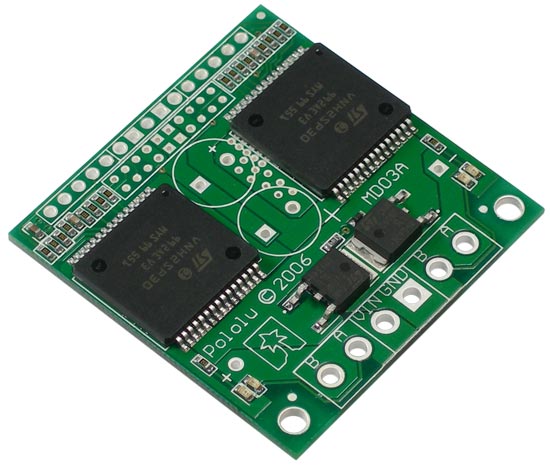
Dual VNH2SP30 Motor Driver Carrier MD03A
OFERTA POR RENOVACION DE STOCK!!! Driver para dos motores DC de 5.5V a 16V, con una capacidad de corriente de 30 Amper (pico), diseñado y fabricado por Pololu. Incluye borneras y capacitores (sin soldar).
COD: P000708
Peso: 0.001 Kg
Disponibilidad: En Stock
ARS 11990.00
El producto no está disponible para la venta en este momento
Características
If you are looking to drive two high-power motors through one compact unit, these dual VNH2SP30 motor driver carriers are perfect for you. With these boards, it's easy to get a medium-sized, differential drive robot running in no time. Includes current sensing and can operate at 20 KHz PWM frequency.
Overview
 |
The Pololu dual high-power motor drivers is a compact carriers for the VNH2SP30 motor driver integrated circuits from ST. The board incorporates most of the components of the typical application diagram on page 8 of the VNH2SP30 datasheet, including pull-up and current-limiting resistors and a FET for reverse battery protection. To keep the number of I/O lines down, the two enable/diagnostic lines on each chip are tied together. All you need to add is a microcontroller or other control circuit to turn the H-Bridges on and off.
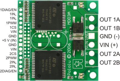 |
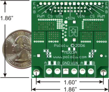
In a typical application, the power connections are made on one end of the board, and the control connections are made on the other end. +5 volts must be supplied to the board through the smaller 0.1"-spaced pins; the input voltage is available at those pins as well, but the connection is not intended for currents exceeding a few amps. The diagnostic pins can be left disconnected if you do not want to monitor the fault conditions of the motor drivers. INA and INB control the direction of each motor, and the PWM pins turns the motors on or off. The current sense (CS) pins will output approximately 0.13 volts per amp of output current.
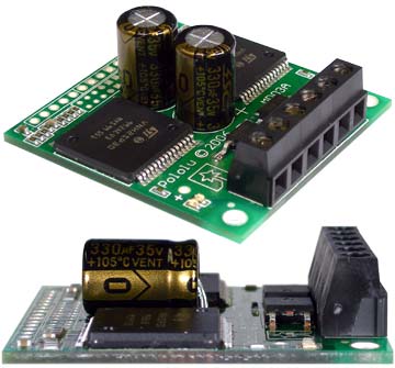 |
The dual motor driver PCB includes provisions for installing up to three large capacitors to limit disturbances on the main power line. Two 10mm radial capacitors may be mounted between the motor driver ICs, and an axial capacitor may be mounted between the ICs and power connections. It is generally not necessary to use all three capacitors; two radial capacitors are included with each unit. For applications that require a low profile, a single capacitor can be installed on its side as shown in the picture to the right.
Note: A 15-pin male header, three 2-pin terminal blocks, and two electrolytic capacitors are included but not soldered onto the boards. No printed documentation is shipped with these items; please see the VNH2SP30 datasheet.
Specifications
| Operating supply voltage (Vcc) | 5.5 - 16 V |
| Maximum current rating | 30 A |
| MOSFET on-resistance (per leg) | 19 mO |
| Maximum PWM frequency | 20 kHz |
| Current sense | approximately 0.13 V/A |
| Over-voltage shutoff | 16 V minimum (19 V typical) |
| Time to overheat at 20 A** | 35 seconds |
| Time to overheat at 15 A** | 150 seconds |
| Current for infinite run time** | 14 A |
*Manufacturer specification. In our experience, shoot-through currents make PWM operation impractical above 16 V.
**Typical results using Pololu motor driver carrier with 100% duty cycle at room temperature.
Real-world power dissipation considerations
The motor drivers have maximum current ratings of 30 A continuous. However, the chips by themselves will overheat at lower currents (see table above for typical values). The actual current you can deliver will depend on how well you can keep the motor drivers cool. The carrier printed circuit board is designed to draw heat out of the motor driver chips, but performance can be improved by adding a heat sink. In our tests, we were able to deliver short durations (on the order of milliseconds) of 30 A and several seconds of 20 A without overheating. At 6 A, the chip gets just barely noticeably warm to the touch. For high-current installations, the motor and power supply wires should also be soldered directly instead of going through the supplied terminal blocks, which are rated for up to 15 A.
This product can get hot enough to burn you long before the chip overheats. Take care when handling this product and other components connected to it.
Many motor controllers or speed controllers can have peak current ratings that are substantially higher than the continuous current rating; this is not the case with these motor drivers, which have a 30 A continuous rating and over-current protection that can kick in as low as 30 A (45 A typical). Therefore, the stall current of your motor should not be more than 30 A. (Even if you expect to run at a much lower average current, the motor can still draw high currents when it is starting or if you use low duty cycle PWM to keep the average current down.)
 |
|
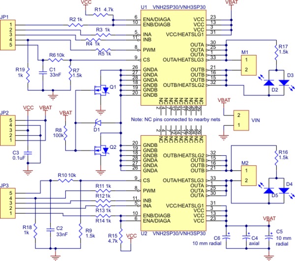
Schematic of the Pololu Dual High Current Motor Driver Carrier |
|---|
Galería de Imágenes


Archivos
Comentarios
Escribir ComentarioOpenHacks (01/10/2015 - 17:22)
Bruno, esta es la información de la hoja de datos: Current for infinite run time** --> 14 A. Time to overheat at 20 A** --> 35 seconds. Time to overheat at 15 A** --> 150 seconds. Los 30A son un valor máximo pico, de muy escasa duración. La corriente nominal serían 14A. Saludos!
Bruno (01/10/2015 - 14:52)
Disculpa. Puedo manejar hasta 30A por cada salida?.
OpenHacks (01/10/2015 - 09:12)
Hola Bruno, si, es igual con el formato levemente distinto. Saludos!
bruno (01/10/2015 - 04:36)
Hola, consulto. este driver es igual que el monster moto shield de sparkfun?.